This application note explains the procedure for testing FR2 using Amarisoft UE Simbox MBS and an exernal UDC (Up Down Converter) box.
|
Note that UE Simbox MBS can support a minimum k2 value equal to 4. |
Following section gives you a brief background on how a UDC works. Next chapters explain how to cable, install and configure the UDC and UE Simbox. Please note that this procedure is only applicable to UE Simbox MBS. Other UE Simbox types can not be upgraded to FR2.
Amarisoft UE Simbox MBS is equipped with SDR100 cards. These SDR cards have 100 MHz of cell bandwith and are able to receive and transmit signals with frequencies from 300 MHz up to 6 GHz. In order to be able to test in mmwave, this sub-6 signal needs to be shifted to a higher frequency within the specified FR2 bands. This is done by using an external frequency shifter called UDC. The UDC has a local oscillator (LO) with a mixer to change the frequency of an input signal. This frequency conversion process produces a signal which is the sum of the frequency of the local oscillator (LO frequency) and the frequency of the input signal (IF frequency) at the transmission side. At reception side, it produces a signal which is the difference between the received mmwave signal and the LO frequency.
Simply put, at the TX side, the output frequency of the UDC is the sum of the SDR card TX frequency and the UDC LO frequency. At RX side, the input frequency of the SDR card RX1 is the difference between the received mmwave signal and the LO frequency.
RF Freq at the output of UDC (RF1) = IF (SDR TX1) + LO Freq
IF at the input of the SDR card (RX1) = RF Freq (UDC RF2) - LO Freq
Amarisoft UE Simbox MBS can support UDC type
UDCB4 has 4 channels (RF-1, RF-2, RF-3, RF-4), it can support MIMO 2x2 functionality. UDCB4 has different SKUs to support different frequencies.
The following table summarizes the supported frequency range of each model/SKU as well as the the list of corresponding FR2 bands.
| UDC Model | Channels | Freq Range | FR2 bands |
|---|---|---|---|
| UDCB4-2430 | 4 | 24-30 GHz | n257,n258,n261 |
| UDCB4-3748 | 4 | 37-48 GHz | n259,n260,n262 |
This chapter explains how to cable the UDC with Amarisoft UE Simbox. A connection diagram is detailed for following use cases:
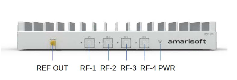
The following images depict the front and rear view of UDCB4.
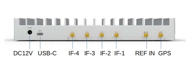
The IF ports correspond to the IF frequency at the input of the UDC and should be connected to the SDR cards according to the use case. The RF ports correpond to the FR2 signal and should be connected to the horn antennas. DC 12V power port is to be conncted to the provided power supply. The USB port is to be connected to the Simbox for UDC configuration.
The device connection is depicted below:

|
The UDC should be enumerated as |
The following diagram depicts the cabling for one cell FR2 MIMO 2x2. We assume that SDR0/SDR1 are used for LTE and SDR2 for FR2.
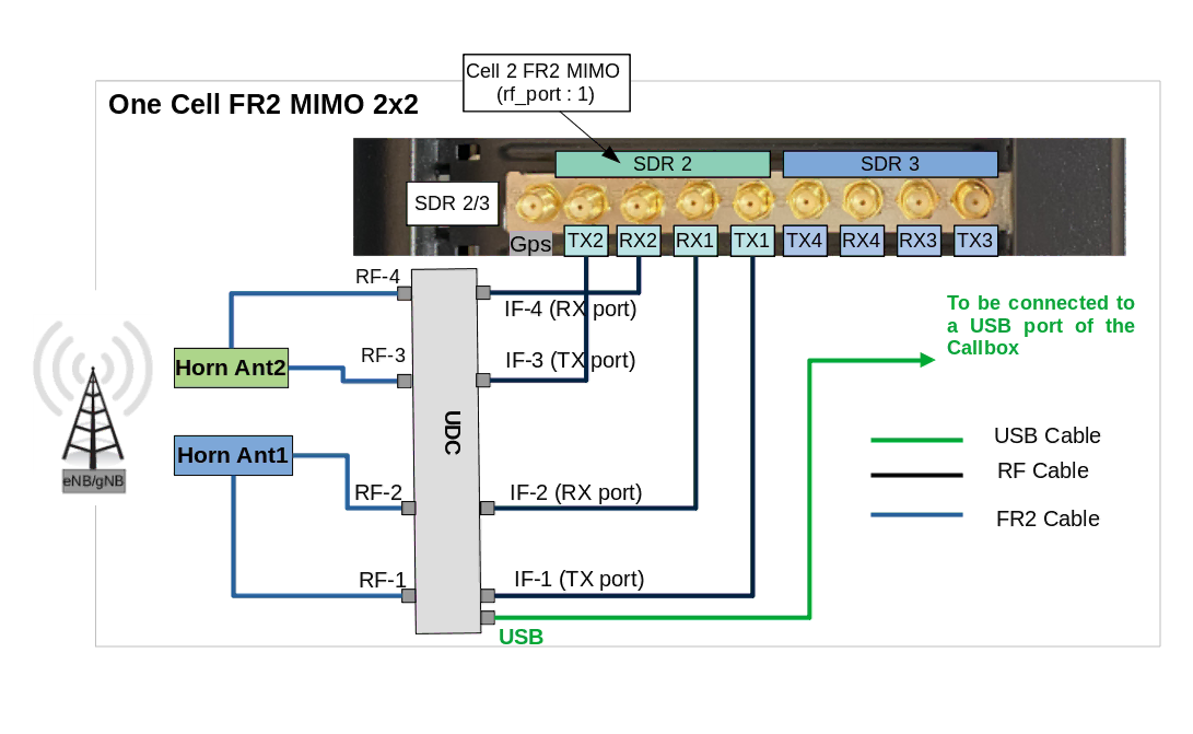
We have assumed that in the config file we have set rx_antenna: "rx", which means RF connection in TDD is the same as for FDD. We have also assumed that the device connection part as explained in the previous section has been done.
The setup of the UDC is as follows:
The procedure is exactly same as the previous section except that the IF input of each UDC is connected to a RF combiner. TX1 of cell 1, cell2 up to cell4 are combined and fed into IF1 port of the UDC. RX1 of cell 1, cell2 up to cell4 are combined and fed into IF2 port of the UDC and so on.

The TX side could be simplified if there is no MIMO in UL by removing the IF3 input. When testing carrier aggregation, usually the UL signal comes only from the primary cell. In this case, the IF4 could be directly connected to the primary cell TX1 port.
This chapter goes through UDC and UE Simbox configuration.
UDCs are configured automatically through "udc-auto-cfg.sh" script available under "/root/ue/config/" folder. This script configures automatically the following parameters:
IF frequency: It selects the best SDR frequency based on SDR performances and UDC specification
LO frequency: It computes the correct UDC LO frequency based on FR2 RF frequency (FR2 cell arfcn) and UDC IF frequency
tx_gain: It computes the tx_gain of each rf_port to avoid UDC IF port saturation
"udc-auto-cfg.sh" script is called directly by the ue config file.
It is also possible to configure the UDC manually without calling udc-auto-cfg.sh script. For that, you can refer to UDC user manual.
on ue config file, we define:
udc_ports global array, which is composed by one or multiple objects. Each object configures one physical UDC device that is connected to one or several FR2 cells.
udc_port parameter in cells object. It corresponds to the udc device index in udc_ports array that is connected to the FR2 cell(s).
tx_power_offset parameter in cells object, See tx_power_offset computation.
Each udc_ports object configures the following parameters:
cmd: path to UDC configuration script. The default script path is /root/ue/config/
args: string, UDC configuration script input parameters. Each parameter is separated by semicolon. The configurable parameters are:
lo_freq: optional float, specify UDC LO frequency in MHz. If not present, it will be automatically computed by udc-auto-cfg.sh script based on suitable SDR IF frequency and UDC specification. We recommend to keep it to default value.
The example below assumes that SDR2 (mapped on rf_port 2), handling FR2 cell MIMO 2x2, is connected to UDC. The UDC is mounted as /dev/ttyUSB0.
In this example UDC parameters clock, tx rx and lo_freq are set to default. It means that the UDC is configured with internal clock, IF1 and IF3 are the UDC TX ports, IF2 and IF4 are the UDC RX ports, the LO frequency is computed automatically by the udc-auto-cfg.sh script.
rf_driver: {
    name: "sdr",

    /* list of devices. 'dev0' is always the master. */
    args: "dev0=/dev/sdr0,dev1=/dev/sdr1,dev2=/dev/sdr2",

    /* TDD: force the RX antenna on the RX connector */
    rx_antenna: "rx",
},

udc_ports: [
  // udc_port index 0
  {
    cmd: "/root/ue/config/udc-auto-cfg.sh",
    args: "/dev/ttyUSB0",
  },
],

cells: [
  {
    rf_port: 2,
    bandwidth: CELL_BANDWIDTH,

    udc_port: 0,
    tx_power_offset:IF_ATTENUATION,

    band: 257,
    dl_nr_arfcn: 2079167,
Let’s now change the UDC configuration and try to set the clock to external 10MHz clock, use IF1/IF2 as TX ports and TF3/IF4 as RX ports and finally configure the LO frequency to 25GHz. In this case the configuration should be as follow:
rf_driver: {
    name: "sdr",

    /* list of devices. 'dev0' is always the master. */
    args: "dev0=/dev/sdr0,dev1=/dev/sdr1,dev2=/dev/sdr2",

    /* TDD: force the RX antenna on the RX connector */
    rx_antenna: "rx",
},

udc_ports: [
  // udc_port index 0
  {
    cmd: "/root/ue/config/udc-auto-cfg.sh",
    args: "/dev/ttyUSB0;clock=external;tx=1,2;rx=3,4",
    lo_freq: 25000,
  },
],

cells: [
  {
    rf_port: 2,
    bandwidth: CELL_BANDWIDTH,

    udc_port: 0,
    tx_power_offset:IF_ATTENUATION,

    band: 257,
    dl_nr_arfcn: 2079167,
|
Note that RF cabling between SDR card and UDC should adjusted according to the new UDC configuration. Also UDC ref clock should be connected to an extenal 10MHz clock generator |
IF_ATTENUATION corresponds to the attenuation in dB between SDR TX port and the UDC IF port. It is used for tx_gain automatique computation of each rf port to avoid UDC saturation. The default value is 0, in case of aggregated cells using a combiner the attenuation is computed as -10*log10(NB COMBINER PORTS), eventual additional attenuators need to be added to this value.
tx_power_offset:0
tx_power_offset:-9
tx_power_offset:-11
tx_power_offset:-21
ue-nsa-fr2.cfg could be used for NSA mmwave testing. This file configures one LTE cell and one FR2 cell.
FR2 cell is mapped on rf_port 1 which corresponds to SDR1 in our example. SDR1 is directly connected to udc_port 0 without any attenuation.
In this example UDC parameters clock, tx rx and lo_freq are set to default. It means that the UDC is configured with internal clock, IF1 and IF3 are the UDC TX ports, IF2 and IF4 are the UDC RX ports, the LO frequency is computed automatically by the udc-auto-cfg.sh script.
  rf_driver: {
    name: "sdr",
    args: "dev0=/dev/sdr0,dev1=/dev/sdr1",
    rx_antenna: "rx",
  },

  udc_ports: [
    // udc_port index 0
    {
      cmd: "/root/ue/config/udc-auto-cfg.sh",
      args: "/dev/ttyUSB0",
    },
  ],

  cell_groups: [
  {
    group_type: "lte",
    ...
    cells: [{

      rf_port: 0,
      ...

    }],
  },
  {
    group_type: "nr",
    ...
    cells: [{
      rf_port: 1,
      bandwidth: 100,

      udc_port: 0,
      tx_power_offset:0,

      band: 257,
      dl_nr_arfcn: 2079167, // 28000.08 MHz

      rx_to_tx_latency: 4,

      ...

    }],
  }],
The parameter rx_to_tx_latency could also be used to increase the data rate in FR2. This parameter defines the minimum allowed latency in slots between RX and TX.
The minimum supported value is 4. As a consequence the minimum supported k2 value is 4.
ue-sa-fr2.cfg could be used for SA mmwave testing. This file configures one FR2 cell is SA mode.
FR2 cell is mapped on rf_port 0 which corresponds to SDR0 in our example. SDR0 is directly connected to udc_port 0 without any attenuation.
In this example UDC parameters clock, tx rx and lo_freq are set to default. It means that the UDC is configured with internal clock, IF1 and IF3 are the UDC TX ports, IF2 and IF4 are the UDC RX ports, the LO frequency is computed automatically by the udc-auto-cfg.sh script.
  rf_driver: {
    name: "sdr",
    args: "dev0=/dev/sdr0",
    rx_antenna: "rx",
  },

  udc_ports: [
    // udc_port index 0
    {
      cmd: "/root/ue/config/udc-auto-cfg.sh",
      args: "/dev/ttyUSB0",
    },
  ],

  cell_groups: [{
    group_type: "nr",
    ...
    cells: [{
      rf_port: 0,
      bandwidth: 100,

      udc_port: 0,
      tx_power_offset:0,

      band: 257,
      dl_nr_arfcn: 2079167, // 28000.08 MHz
      rx_to_tx_latency: 4,

      ...

    }],
  }],
The parameter rx_to_tx_latency could also be used to increase the data rate in FR2. This parameter defines the minimum allowed latency in slots between RX and TX.
The minimum supported value is 4. As a consequence the minimum supported k2 value is 4.
UE Simbox MBS can support up to 4 cells in FR2.
Four FR2 cells are mapped to rf_port 1, 2, 3 and 4 which corresponds to SDR1, SDR2, SDR3 and SDR4 in our example. SDR1, SDR2, SDR3 and SDR4 are connected to udc_port 0 through an RF combiner 4 to 1 (thus tx_power_offset equals to -10*log10(4) ~-6dB).
In this example UDC parameters clock, tx rx and lo_freq are set to default. It means that the UDC is configured with internal clock, IF1 and IF3 are the UDC TX ports, IF2 and IF4 are the UDC RX ports, the LO frequency is computed automatically by the udc-auto-cfg.sh script.
  rf_driver: {
    name: "sdr",
    args: "dev0=/dev/sdr0,dev1=/dev/sdr1,dev2=/dev/sdr2,dev3=/dev/sdr3,dev4=/dev/sdr4",
    rx_antenna: "rx",
  },

  udc_ports: [
    // udc_port index 0
    {
      cmd: "/root/ue/config/udc-auto-cfg.sh",
      args: "/dev/ttyUSB0",
    },
  ],

  cell_groups: [
  {
    group_type: "lte",
    ...
    cells: [{

      rf_port: 0,
      ...

    }],
  },

  {
    group_type: "nr",
    ...
    cells: [
    {

      rf_port: 1,
      bandwidth: 100,

      udc_port: 0,
      tx_power_offset:-6,

      band: 257,
      dl_nr_arfcn: 2079167,
      ssb_nr_arfcn: 2079163,

      rx_to_tx_latency: 4,

      ...
    },
    {
      rf_port: 2,
      bandwidth: 100,

      udc_port: 0,
      tx_power_offset:-6,

      band: 257,
      dl_nr_arfcn: 2080833,
      ssb_nr_arfcn: 2080891,

      rx_to_tx_latency: 4,

      ...
    },
    {
      rf_port: 3,
      bandwidth: 100,

      udc_port: 0,
      tx_power_offset:-6,

      band: 257,
      dl_nr_arfcn: 2082499,
      ssb_nr_arfcn: 2082331,

      rx_to_tx_latency: 4,

      ...
    },
    {
      rf_port: 4,
      bandwidth: 100,

      udc_port: 0,
      tx_power_offset:-6,


      band: 257,
      dl_nr_arfcn: 2084165,
      ssb_nr_arfcn: 2084059,

      rx_to_tx_latency: 4,

      ...
    }

    ],
  }],
This document is copyright (C) 2012-2025 Amarisoft. Its redistribution without authorization is prohibited.
This document is available without any express or implied warranty and is subject to change without notice. In no event will Amarisoft be held liable for any damages arising from the use of this document.
For any technical issue, please raise a ticket from our support site at https://support.amarisoft.com/.
To learn more about our technology and solutions, e-mail us at customer@amarisoft.com or visit https://www.amarisoft.com.