This application note explains how to calibrate Amarisoft PCIe SDR card.
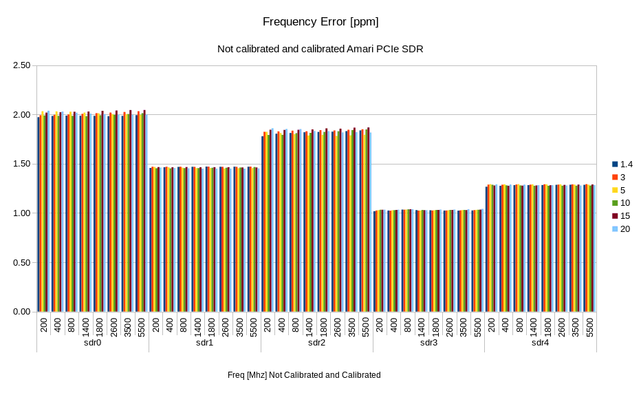
Amarisoft PCIe card has a maximum frequency error less than 2 ppm. The following figure depicts the measured frequency error on a sample of 5 cards.
Start lteenb with a 10 MHz SISO FDD cell and dl_earfcn corresponding to Fset MHz. Connect the TX1 SDR connector to an analyzer. Set the Fset as central frequency of the signal analyzer. Read Fmeasured or Fmeasured-Fset from the signal analyzer, then compute:
Ferror = 10^-6 * (Fmeasured - Fset)/Fset
In general
|Ferror|< 2 ppm
This error does not depend on the bandwidth or the frequency. It only depends on the SDR HW.
This error can be corrected by using the following command
/root/trx_sdr/sdr_util clock_tune -<Ferror in ppm>
As an example, if Ferror = 1.6 ppm then the command to use is
/root/trx_sdr/sdr_util clock_tune -1.6
if Ferror = -1 ppm then the command to use is
/root/trx_sdr/sdr_util clock_tune 1
Note that the setting is power cycle persistent. In case you have many SDRs connected to the PC, use the option -c device_num to select the device (default = all)
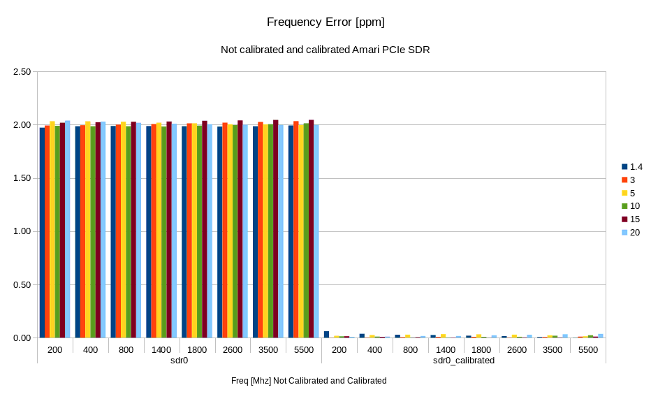
After calibration, you can expect Ferror < 0.1 ppm. The following figure shows the frequency error on a calibrated and non calibrated PCIe SDR cards.
Since test release version 2019-10-31, frequency calibration can be performed via GPS signal. To calibrate a SDR card, stop the lte service
service lte stop
connect a GPS antenna to the âGPSâ SMA connector of the SDR card.
Any active GPS antenna accepting a 3.3V DC supply can be used, for example:
http://www.mouser.fr/Search/ProductDetail.aspx?R=ANT-GPS-SH-SMAvirtualkey59000000virtualkey712-ANT-GPS-SH-SMA
You can check the GPS state with
./sdr_util gps_state
The GPS might takes a few minutes to lock.
Under /root/trx_sdr/ folder execute
./sdr_util -c <n> gps_cal <t> -s
where:
<n> sdr device number
<t> GPS clock acquisition time in seconds, 30 seconds is a good value
-s option to store the resulting ppm correction to a flash memory on the card
If you use an Amarisoft product where the master sdr0 provides the clock to the other slave cards, you only need to calibrate the master card
./sdr_util -c 0 gps_cal 30 -s
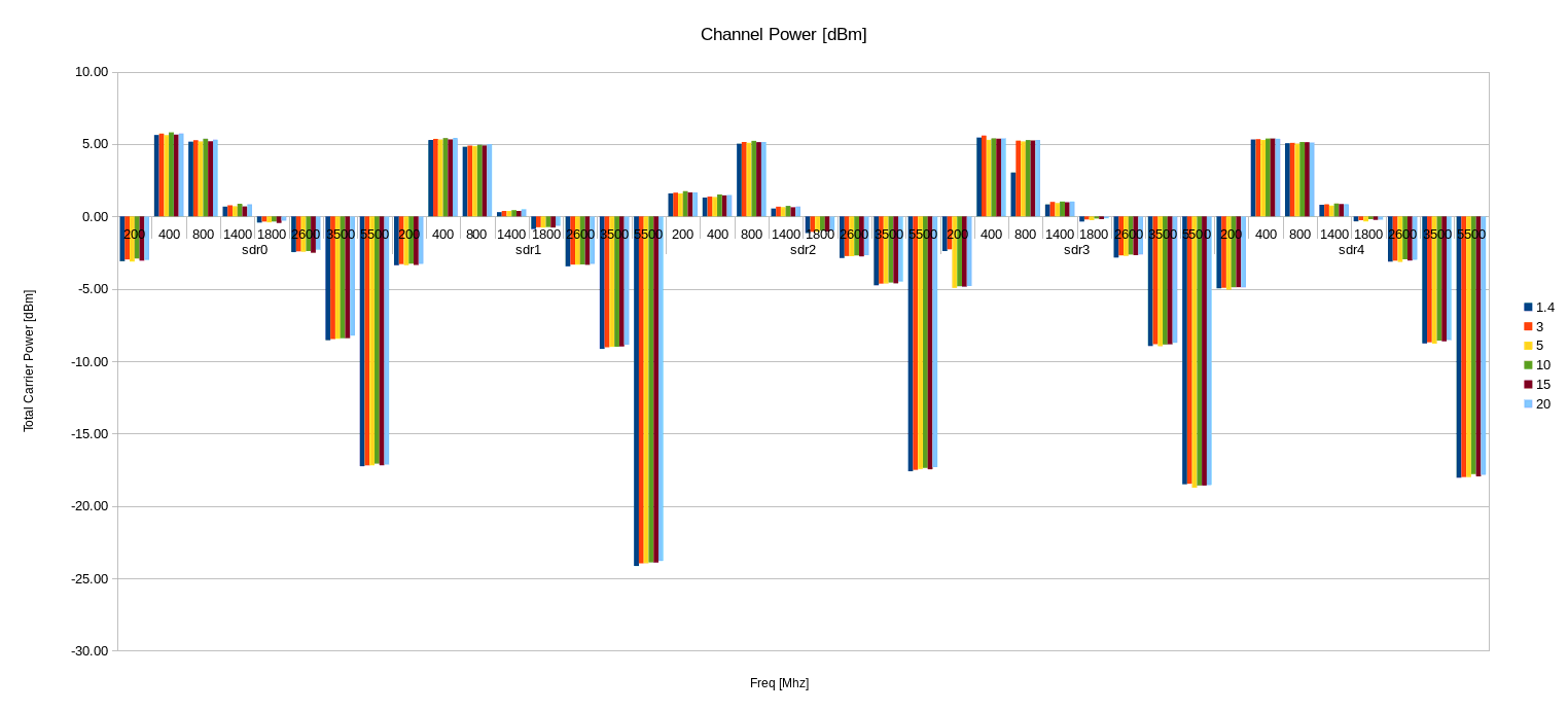
The channel power is the integrated power over the cell bandwidth. The downlink power of the Amarisoft PCIe SDR card depends on the frequency and varies roughly between +5 dBm and -10 dBm for f < 3500 MHz, and can go down to -25 dBm for higher frequencies as can be viewed in the following figure.
You can measure the channel power for each frequency using the attached eNodeB config and measuring with a power meter the integrated power over the bandwidth. You can do this for each unit you want to calibrate and keep the value in a table (Channel power for 20 MHz versus Frequency).
for f = fmin;f<fmax;f=fdeta
    Set the frequency in the config file to f, and run enb (dl_freq_min parameter in the attached config )
    Set the frequency and bandwidth in the power meter
    Capture the channel power from the power meter
end for
Note that the measurement shall be taken with a BW = 20 MHz and tx_gain=90.
Note 2 any path loss shall be added to the value read from the power meter.
Note 3 The more fdelta is small the more accurate will be the interpolation.
To achieve a certain channel power, you know the value for tx_gain = 90 from the calibration array (or interpolation of the values), then you can select the right tx_gain to achieve you target channel gain.
To achieve a certain RSRP, you have to convert the RSRP value to channel power using the target bw value, then you use the method for channel power.
In order to calibrate the UL power of the card, you can split the uplink signal to both eNodeB and power meter. Make sure you add a 3 dB attenuation in the dl path as well to have the same path loss in both directions. Then you can compare the power reported by the eNodeB, with the one reported by the power meter.
The initial value of the rx_gain set in the configuration file is taken into account when the eNodeB computes the uplink power. But if you change the value during the execution using the rx_gain command line interface, then you have to apply the rx_gain delta between the new value and the one in the configuration file by yourself. We recommend not to change the rx_gain value dynamically.
This document is copyright (C) 2012-2024 Amarisoft. Its redistribution without authorization is prohibited.
This document is available without any express or implied warranty and is subject to change without notice. In no event will Amarisoft be held liable for any damages arising from the use of this document.
For any technical issue, please raise a ticket from our support site at https://support.amarisoft.com/.
To learn more about our technology and solutions, e-mail us at customer@amarisoft.com or visit https://www.amarisoft.com.